Scope Mode
See the latest version. This site is no longer maintained.
See the latest version for up-to-date documentation. Docs have been completely reworked and moved to a new location. The new site is more user-friendly and searchable. It's also easier for the developers to work with.
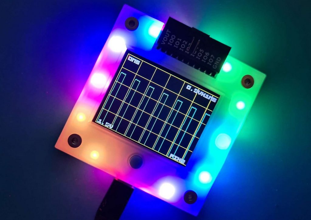
The Bus Pirate can support an oscilloscope display mode - it's limited by the underlying RP2040 chip to 0.5Msps so it's suitable for analog audio, not for high speed digital signals greater than 500KHz. Analog signals can be captured on any IO pin.
Start the scope
Display selection
1. Default
2. Scope
x. Exit
Display > 2
Display: Scope
The d command selects the LCD display mode.
- Choose
scopeto load the oscilloscope on the Bus Pirate LCD - You should see an oscilloscope show up on the Bus Pirate screen
- It's rotated 90 degrees from the normal orientation so we can show longer waveforms
Display overview

The display is small, to make the scope more useful we have a much larger capture buffer than the actual display and software scales the captured data to fit. The actual resolution is 0.5M samples per second. In the 100uS/div range that's one sample per pixel, any faster (50uS/div and below and samples are interpolated on the screen). If possible we try and capture up to 10 samples per pixel at whatever the current resolution is so that you can zoom into captured data at least 10 times (3 steps) before we start interpolating.
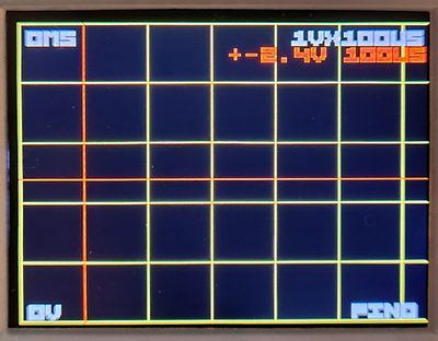
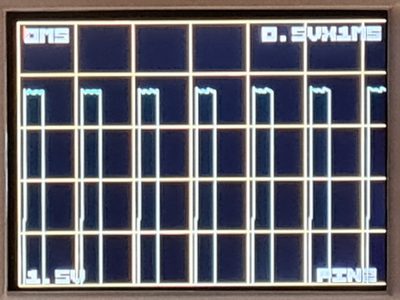
- The text '1V x 100uS' in the top right is the scale (voltage X time), the size of 1 yellow square on the screen. The default scale is "1V x 100uS" - 1 volt by 100 microseconds
- The text '0mS' in the top left is the offset (in time) of the left hand vertical yellow line
- The text '0V' in the bottom left is the offset (in volts) of the bottom yellow line
- The text 'PIN0' in the bottom right tells you which input pin is being sampled
- If the trigger point for the current trace is visible on the display then a small red arrow will appear at the trigger point at the top of the display
By default the screen displays 0V-5V in the vertical direction and 0uS to 640uS horizontally. The data on the screen is a window into a larger display buffer. After taking a trace you can move around inside the buffer to explore different sections of the data.
Commands
Controls are done from the command line, just like other Bus Pirate functions. There are 5 commands that can be entered:
- sr {pin} {mode} - Scope Run, optional capture {pin} (0-7) and/or {mode} ("o n a" Once, Normal, Auto)
- ss - Scope Stop
- x - Edit timebase (x axis)
- y - Edit voltage (y access)
- t - Edit trigger
All of these commands enter a more interactive UI where you can type single characters to navigate the captured data. You can skip back out to the normal UI by typing ENTER.
Scope Run
sr {pin} {mode} ('scope run') starts the oscilloscope, you can specify additional parameters if you don't specify any it will use the previous settings.
{pin} is a single digit 0-7 to specify which Bus Pirate pin to capture.
{mode} is 'o' 'n' or 'a' to specify which mode you want the display to work in:
o('once') will wait for a single trigger and stopn('normal') will wait for a trigger, display the waveform and restart looking for the next triggera('auto') will wait for a trigger or a timeout (a second or so) whichever comes first and then restart, use this one to measure voltages
Scope Stop
ss ('scope stop') stops the scope
Scope Parameters
In addition there are 3 commands than can be used to alter parameters - these replace the knobs you'd find on a normal oscilloscope:
x('x axis' - timebase)y('y axis' - voltage)t('trigger' - trigger voltage and position)
These commands work a bit differently from normal Bus Pirate commands, you can use them two ways, either type the command along with some parameters and hit enter, or just type the command and enter and you will pop into an interactive mode where you can type parameters to change things interactively on the display, typing enter again will return you to the main BusPirate prompt.
X/Y navigation
Timebase: +- ^vT ty rsona> +-
LED-()> y
Voltage scale: +- ^vT tx rsona> +-
Interactive parameters in x and y modes are:
+/-in x mode increases or decreases the timebase scale - it changes the displayed scale but not the underlying data until the next time data is collected.+/-in y mode increases or decreases the voltage sensitivity (change the displayed scale)^/v/</>or the equivalent arrow keys in x or y modes moves the display around within the currently collected data
Triggers
Trigger: +-*b ^vT BME xy rsona>
In Trigger mode
+/-/b/nchanges which edge triggers a data capture (positive going, negative going, both edges or no edges respectively)^/vor the equivalent arrow keys changes the voltage at which the trigger occurs</>or the equivalent arrow keys moves the next trigger point around (chooses where in the next set of collected data the trigger will be)B/M/Emoves the trigger point to the beginning/middle/end of the sample buffer
In trigger mode you will see a red crosshair that shows the time and voltage that the trigger occurs at, there's also red test that describes it. If the crosshair is off the screen you'll see a red arrow pointing at where it's located.
In all 3 modes you can type:
Tmoves the x display point to show the current trigger pointrstart run (likesr)sstop the scope (likess)ostart the scope in once mode (likesr o)nstart the scope in normal mode (likesr n)astart the scope in auto mode (likesr a)tswitch to trigger modexswitch to x/timebase modeyswitch to y/voltage modeenterleaves interactive mode
Note: commands that require a shift like + can also use their unshifted equivalents (= for +).
The general idea is that you switch into scope display mode with "d", start the scope running with something like "sr 2n" to sample from pin 2, use "t" to set up a trigger use "x" to get into interactive mode and +/- to set up timebase and the arrow keys to look at the result
Quick Tutorial
Here's a quick start tutorial using only the Bus Pirate hardware. We're going to work on pin # 2, initially wagging it up and down and then setting up a clock.
Setup
Mode selection
1. HiZ
2. 1-WIRE
3. UART
4. I2C
5. SPI
6. LED
x. Exit
Mode > 6
LED type
1. WS2812/SK6812/'NeoPixel' (single wire interface)*
2. APA102/SK9822 (clock and data interface)
3. Onboard LEDs (16 SK6812s)
x. Exit
Type (1) > 3
Mode: LED
LED-()> W
Power supply
Volts (0.80V-5.00V)
x to exit (3.30) >
3.30V requested, closest value: 3.30V
Set current limit?
n
Power supply:Enabled
Vreg output: 3.3V, Vref/Vout pin: 3.3V, Current sense: 2.4mA
LED-()>
Enter LED mode and enable a 3.3volt power supply:
- Enter a mode with the
mcommand, select LED mode with onboard LEDs - Set the I/O power supply to 3.3volts using the 'w' command (w
enterenternenter)
Enable Scope
Display selection
1. Default
2. Scope
x. Exit
Display > 2
Display: Scope
The d command selects the LCD display mode.
- Type
dandenterto configure the display mode - Choose
scopeto load the oscilloscope on the Bus Pirate LCD - You should see an oscilloscope on the Bus Pirate screen
Triggers
Trigger: +-*b ^vT BME xy rsona> b
LED-()> sr 2n
Set the trigger to 'both' edges and begin the scope capture on pin 2:
- Type
tandenterto get into trigger mode. - Press
bto set triggers on both the rising and falling edges, thenenterto exit sr 2nthenenterto start the scope on pin 2 in normal mode
The default trigger point is ~2.4volts.
Capture
Pull-up resistors: Enabled (10K ohms @ 3.3V)
LED-()> p
Pull-up resistors: Disabled
LED-()>
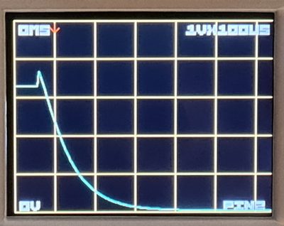
Now we'll use the pull-up resistors to trigger the scope:
Pandenterto turn on the pull-up resistors. You should see a trace with a rising edgepandenterto turn off the pull-up resistors. You should see a nice exponential decay curve on the scope as pin 2's capacitance discharges

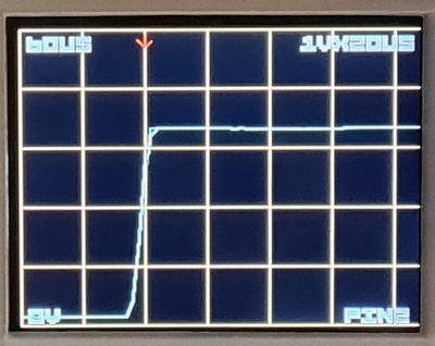
Edge triggers
Pull-up resistors: Enabled (10K ohms @ 3.3V)
LED-()> t
Trigger: +-*b ^vT BME xy rsona> +
LED-()> p
Pull-up resistors: Disabled
LED-()> P
Pull-up resistors: Enabled (10K ohms @ 3.3V)
LED-()>
The scope can be triggered by the rising or falling edge of a signal, or both:
Pandenterto turn on the pull-up resistors again.tandenterto configure the trigger. Type+to trigger only on rising edges, thenenterto leave trigger modepandenterto turn off the pull-up resistors. This time the scope doesn't capture because the signal is a falling edgePandenterto turn on the pull-up resistors again. The scope is triggered by the rising edge.
Navigation
Generate frequency
Choose available pin:
2. IO2
3. IO3
4. IO4
5. IO5
6. IO6
7. IO7
x. Exit
> 2
Period or frequency (ns, us, ms, Hz, KHz or Mhz) > 1ms
Frequency: 1.000ms = 1000Hz (1000.00Hz)
Period: 1000000ns (1.00ms)
Actual frequency: 1000Hz (1.00KHz)
Actual period: 999998ns (1000.00us)
Duty cycle (%) > 33%
Duty cycle: 33.00% = 329999ns (330.00us)
Actual duty cycle: 330000ns (330.00us)
Divider: 31, Period: 64515, Duty: 21290
Generate frequency: Enabled on IO2
LED-()>
Next let's try something more involved, let's set up a square wave on pin 2.
- Generate a frequency on pin 2 (G 2
enter1msenter33%enter)
Time scale
Timebase: +- ^vT ty rsona> +-
You should see the display showing a square wave. The capture buffer is large. We can zoom and pan to navigate the data:
xandenterto scale the X axis (time).- You should see a bunch of square waves, try
+and-to change the scale, and the left and right arrows to move around. Freeze a trace witho
Note you are now in interactive mode - try the - command a few times and see that you can zoom out from the current display and the + zooms in, < and > let you more right and left within the display.
Voltage scale
Voltage scale: +- ^vT tx rsona> +-
Type y on the command line or in the x or t interactive mode type. Now you are in 'voltage mode'. + will zoom in vertically and ^/v will let you scroll up and down.
yandenterto scale the Y axis (volts).- Change the voltage scale with
+and-, and use the up down arrows to move the display
Scroll back to the beginning and use - zoom out to 1v/div. Now type t to go into trigger mode - you'll see a red crosshair showing the trigger voltage and time, and their actual values in red at the top right, you can edit them using the arrow keys, you can also change the trigger type using +-bn - try typing - and seeing how the display changes.
Let's move the trigger point to the middle of the capture buffer - type M and notice how the red vertical line is replaced by a small red arrow pointing right, you can type T to center the display on the new trigger point. BT will put it back.
Limitations and bugs
We're very much limited by the hardware:
- 500k samples per second is the maximum speed of the RP2040 ADC
- 12 bits
- Tiny display
- No way to make a dual scope (we might be able to have a digital trigger in the future)