Blink Some LEDs
See the latest version. This site is no longer maintained.
See the latest version for up-to-date documentation. Docs have been completely reworked and moved to a new location. The new site is more user-friendly and searchable. It's also easier for the developers to work with.

SK6812 RGB LEDs

| Pin | Description |
|---|---|
| VDD | 5 volt power supply |
| DIN | Data Input |
| DOUT | Data Output to next LED |
| GND | Ground |
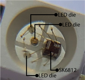
SK6812 RGB LEDs are commonly found in long strips of color changing lights. 3 LED dies (red, blue, green) and an SK6812 controller chip are bonded to a bit of metal called a leadframe. The leadframe is put inside a casing and covered in epoxy. Then the whole thing is baked, like a cake.
The colors are set with a single wire, time-based protocol. Multiple LEDs can be chained together, with the DOUT of one LED connecting to the DIN of the next.
16 of these RGB LEDs are on the Bus Pirate 5 PCB, all wired up and ready to go. We're just going to control one of them because all 16 LEDs at full power would be too much current for some USB ports.
Each LED die in the SK6812 (red, blue, green) uses 20mA at full power. 60mA is required to light all three dies at maximum brightness.
Choose LED Mode
Mode selection
1. HiZ
2. UART
3. I2C
4. SPI
5. LED
6. DUMMY1
x. Exit
Mode > 5
First, enter the Bus Pirate LED control mode.
- Type
mthen pressenterfor the mode menu. - Type
5then pressenterto choose the LED mode.
Configuration
1. WS2812/SK6812/'NeoPixel' (single wire interface)*
2. APA102/SK9822 (clock and data interface)
3. Onboard LEDs (16 SK6812s)
x. Exit
Type (1) > 3
Mode: LED
LED-()>
Now configure the LED mode to use the onboard SK6812 LEDs. Many prompts have a default option in ( ), in this case 1. For this tutorial we want option 3, the onboard LEDs.
- Type
3then pressenter.
Light it up
Data Structure
| Byte # | bit 7 | bit 6 | bit 5 | bit 4 | bit 3 | bit 2 | bit 1 | bit 0 |
|---|---|---|---|---|---|---|---|---|
| 1 | R7 | R6 | R5 | R4 | R3 | R2 | R1 | R0 |
| 2 | G7 | G6 | G5 | G4 | G3 | G2 | G1 | G0 |
| 3 | B7 | B6 | B5 | B4 | B3 | B2 | B1 | B0 |
Each LED is controlled by 24 bits of color information: 8 bits of red, 8 bits of green and 8 bits of blue. That means each LED has 256 brightness levels from 0 to 255.
SK6812 uses GRB (green, red, blue) for the data, but the default format is RGB (red, green, blue). So we use that with Bus Pirate.
Red
RESET
TX: 0b111111110000000000000000.24
LED-()>
Let's start by lighting the red die in the LED. The Bus Pirate understands binary, hexadecimal and decimal formatted numbers. We'll use binary entry first so it's clear exactly how the bits control the LED.
- The data structure table above shows the format for controlling each color in the LED. The first eight bits control red, the next 8 control green and the final 8 control blue.
- Enter the WS2812 bus reset command
[. This command has two purposes. First, it tells the Bus Pirate to process this line as bus syntax. Second, it generates a 50us RESET delay so the LEDs are ready for new data. - Type
0bfor binary entry followed by eight 1s to set the red die to full brightness:0b11111111. - Add
00000000for green and00000000for blue to turn those dies off. - Finally, add
.24to tell the Bus Pirate we want to send 24 bits in one transfer. - The final command is kind of unwieldy:
0b111111110000000000000000.24 - Press
enterto send the command to the LED. The red die should light at full brightness.

Now the pattern for working with the SK6812 starts to become clear. We can enter 0b000000001111111100000000.24 to light the green die, or 0b000000000000000011111111.24 to light the blue die.
=0xFF =255 =0b11111111
LED-()> = 0b00000000
=0x00 =0 =0b00000000
LED-()>
Binary entry is handy because you see exactly what each bit is doing, but that's a lot of 1s and 0s to type every time. Let's have a look at hexadecimal numbers - much shorter and less prone to mistyping.
- The
=command converts between number formats. - Type
= 0b11111111followed byenter. - The Bus Pirate displays the value in hexadecimal (0xff), decimal (255) and binary (0b11111111).
- Do the same for our green and blue bits:
= 0b00000000followed byenter. - The Bus Pirate displays the value in hexadecimal (0x00), decimal (0) and binary (0b00000000).
RESET
TX: 0xFF0000.24
LED-()>
Now let's put it all together and send the same command in hexadecimal.
- Begin with
[to tell the Bus Pirate to expect bus syntax and send a WS2812 RESET command. - Type
0xto tell the Bus Pirate we're writing a hexadecimal number. - Type the value
ff0000.24followed byenter. - The Bus Pirate sends the command.
- Output display mode is set to auto by default, so the Bus Pirate shows the number in the same format it was entered. You can use the
ocommand to change the output display mode. - The LED stays red because we sent the same command in a different number format.
Green
RESET
TX: 0x00FF00.24
LED-()>
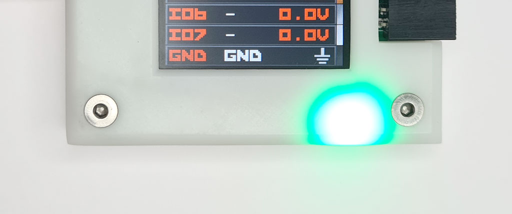
Green is controlled by the second eight bits of data.
- Type
[0x00ff00.24followed byenterto light the green die.
Blue
RESET
TX: 0x0000FF.24
LED-()>
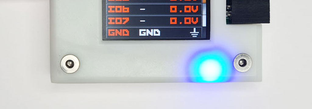
Blue is controlled by the last eight bits of data.
- Type
[0x0000ff.24followed byenterto light the blue die.
Purple
RESET
TX: 0xFF00FF.24
LED-()>
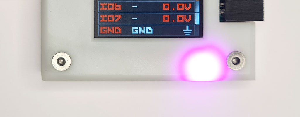
At this point you may wonder if you can mix colors. Why, yes, you can! Let's try red plus blue.
- Type
[0xff00ff.24followed byenter. - The red and blue die light to full brightness.
- The color changes to purple.
White
RESET
TX: 0xFFFFFF.24
LED-()>
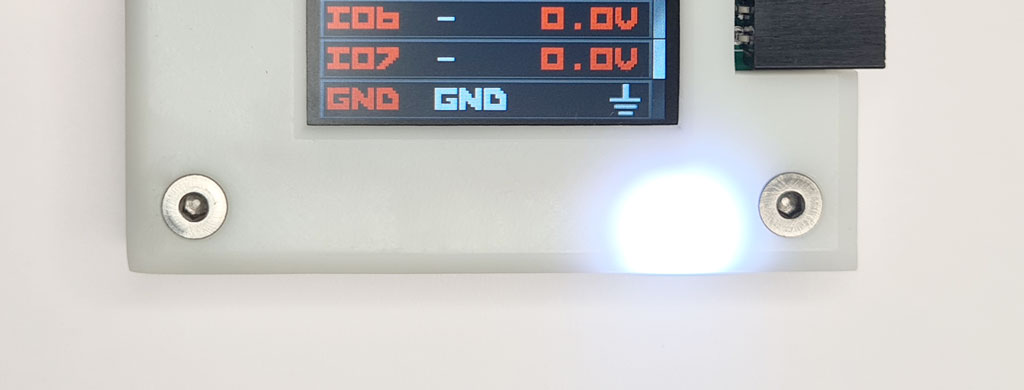
Through the magic of additive color we can make a whole rainbow of tones and shades. We can also make something approximating white light using all three dies.
- Type
[0xffffff.24followed byenter. - All three LED dies light to full brightness.
- The color is a sort of white at the cool (blue) end of the spectrum.
Brightness
=0x80 =128 =0b10000000
LED-()>
Up to this point we've used all the LED dies at full brightness (0xff/255/0b11111111), but we can also control the power level by sending smaller values. Let's reduce the power by half.
- Half of 255 is approximately 128.
- Type
= 128followed byenterto convert 128 to an easier-to-use hexadecimal number. - 0x80 hexadecimal is the same as 128 in decimal notation.
RESET
TX: 0x808080.24
LED-()>
Finally, send a command to set all three dies at half power.
- Type
[0x808080.24followed byenter. - All three LED dies are lit at half power and the brightness is reduced.
- The SK6812 controller chip in the LED uses pulse-width modulation to blink the dies on 50% of the time and off 50% of the time.

Even though the LED dies are only lit 50% of the time it doesn't appear half as bright. This is because human perception of brightness is non-liner. To make it really dim try sending a smaller value like 0x10: 0x101010.24 followed by enter.