IO Pin Descriptions
caution
See the latest version. This site is no longer maintained.
See the latest version for up-to-date documentation. Docs have been completely reworked and moved to a new location. The new site is more user-friendly and searchable. It's also easier for the developers to work with.
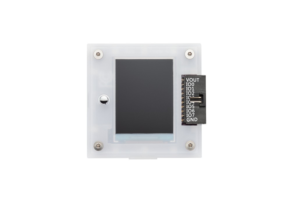
Main connector pinout
| Pin | Name | Description |
|---|---|---|
| 1 | Voltage Out/Voltage Reference (VOUT/VREF) | 1-5volt 400mA onboard power supply output -or- external reference voltage to power the buffers. |
| 2-9 | Input/Output (IO0-IO7) | 8 IO pins with 1.65-5volt buffers, analog voltage measurement, frequency generation, frequency measurement*, toggleable 10K pull-up resistor |
| 10 | Ground (GND) | Ground, connect to ground of test circuit. |
- See Bus Pirate RP2040 pin map below for RP2040 PWM module limitations.
Bus Pirate signal descriptions
| Pin | Description (Bus Pirate is the controller) |
|---|---|
| Master Out Sub In (MOSI/SDO/SDA/TX) | Primary data pin, it's used for bi-directional data transfer in protocols like I2C and 1-Wire, and as data-out from the Bus Pirate in uni-directional protocols like SPI and asynchronous serial (UART). |
| Serial Clock (SCLK/SCL) | Always a clock-out signal from the Bus Pirate. |
| Master In Sub Out (MISO/RX) | Used with protocols that have a dedicated data-input, such as SPI and UART. |
| Chip select (CS) | An output used to activate the serial interface in SPI-like protocols. [ and ] control a dedicated CS pin, but you can use a.X and A.X to take manual control of any available pin. |
| Auxiliary (AUX) | Used as an output or input from the Bus Pirate terminal interface with the A, a, and @ commands. It's useful for protocols that require an additional signal, such as a reset. |
| Voltage Out/Voltage Reference (VOUT/VREF) | 1-5volt, 400mA onboard power supply output -or- external reference voltage to power the buffers. |
| Ground (GND) | Ground, connect to ground of test circuit. |
Bus Pirate RP2040 pin map
| IO Pin | RP2040 Pin | PWM slice | Measure Voltage | Measure Freq. | Freq. Generator | UART | I2C | SPI | LEDs |
|---|---|---|---|---|---|---|---|---|---|
| IO0 | GPIO8 | 4A | Yes | No | Yes, freq tied to IO1 | SDA | SDO | ||
| IO1 | GPIO9 | 4B | Yes | Yes | Yes, freq tied to IO0 | SCL | SCL | ||
| IO2 | GPIO10 | 5A | Yes | No | Yes, freq tied to IO3 | ||||
| IO3 | GPIO11 | 5B | Yes | Yes | Yes, freq tied to IO2 | ||||
| IO4 | GPIO12 | 6A | Yes | No | Yes, freq tied to IO5 | TX | SCLK | ||
| IO5 | GPIO13 | 6B | Yes | Yes | Yes, freq tied to IO4 | RX | MOSI | ||
| IO6 | GPIO14 | 7A | Yes | No | Yes, freq tied to IO7 | MISO | |||
| IO7 | GPIO15 | 7B | Yes | Yes | Yes, freq tied to IO6 | CS |
- RP2040 PWM units consist of a "slice" that drives two adjacent pairs of pins. The duty cycle is independent, but the frequency is shared.
- Only the 'B' part of the slice can measure frequency. The 'A' part cannot be used as a PWM when 'B' is used for frequency measurement.
- Some of these limitations can be addressed with the RP2040 PIO units