SPI Flash Adapters
See the latest version. This site is no longer maintained.
See the latest version for up-to-date documentation. Docs have been completely reworked and moved to a new location. The new site is more user-friendly and searchable. It's also easier for the developers to work with.
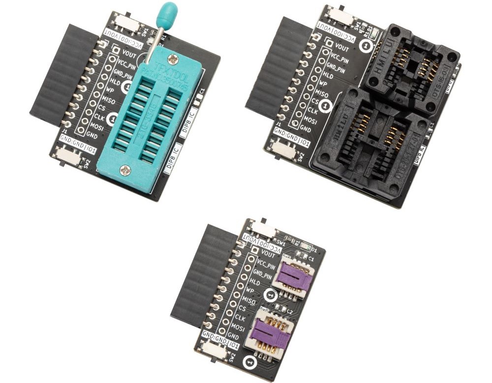
Bus Pirate 5 has a "flash" command to read and write 8 pin SPI flash chips. Soldering chips on breakouts for testing got a bit wasteful, so we whipped up some simple socket adapters that fit the Bus Pirate header.
The sockets on each board are connected with the "most common" SPI flash footprint. Found a chip with a different pinout? Power and ground have a switch that selects between the Bus Pirate VOUT/GND and IO0/IO1 pins for full flexibility.
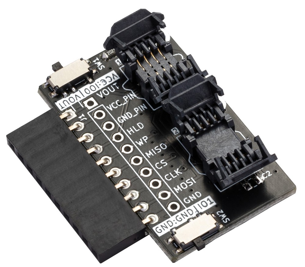
SOP8 SPI Flash Adapter

SOP8 150mil and 208mil are the most common and inexpensive flash packages at the moment. After looking at a number of sockets we decided these bad boys, favorites of the mobile phone repair market, were the way to go. Easy to insert and remove a chip, but a bit bulky with delicate pins. The cost is in the pins, 16 pins cost double that of an 8 pins socket.
Inserting a chip:
- Press down gently on the top of the socket. The spring fingers will retract.
- Place or drop the chip into the socket with the chip pin 1 marker (dot, stripe, etc) aligned with the socket pin 1 marker.
- Release the socket, the spring fingers will grip the chip.
Removing a chip:
- Press down gently on the top of the socket. The spring fingers will retract.
- Gently lift the chip out of the socket with tweezers or turn the socket over and let the chip fall into your hand.
- Release the socket, the spring fingers will close.
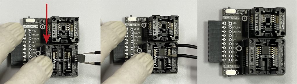
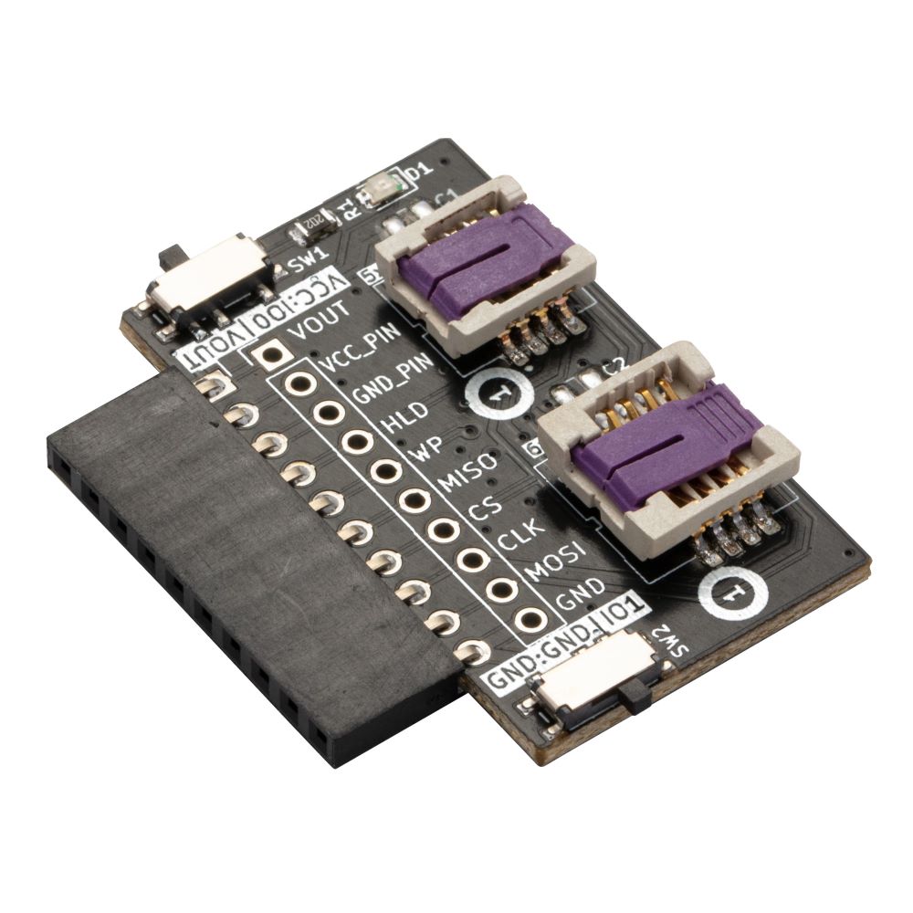
SOP8 LOTES Socket Version
This board also supports 150mil and 208mil SOP8 SPI flash chips using a socket made by LOTES. We like the previous socket better, but these are low profile, easier to carry and more convenient to store. However, they are also more expensive and prone to breaking. There are a limited number of these available if you'd like to compare the sockets yourself.
Inserting a chip:
- Gently lift the top flap of the lid. The is the flap closest to the white circle that marks pin 1 on the PCB.
- Gently lift the lower flap.
- Place or drop the chip into the socket with the chip pin 1 marker (dot, stripe, etc) aligned with the socket pin 1 marker. You may have to align the chip and press down a bit to seat it fully.
- Close the lower flap and then gently close the top flap, pressing it to lock the chip in place.
Removing a chip:
- Gently lift the top flap of the lid. The is the flap closest to the white circle that marks pin 1 on the PCB.
- Gently lift the lower flap.
- Now this is why we don't like the LOTES sockets: the chip is hard to remove. We've had the best success holding the socket upside down and picking the chip out with tweezers.
- Close the lower flap and then gently close the top flap.
The lid flaps are delicate and really prone to snapping off. Be especially careful with opening the socket and removing the chip. We broke more than a few while testing and definitely prefer using the other SOP8 socket.
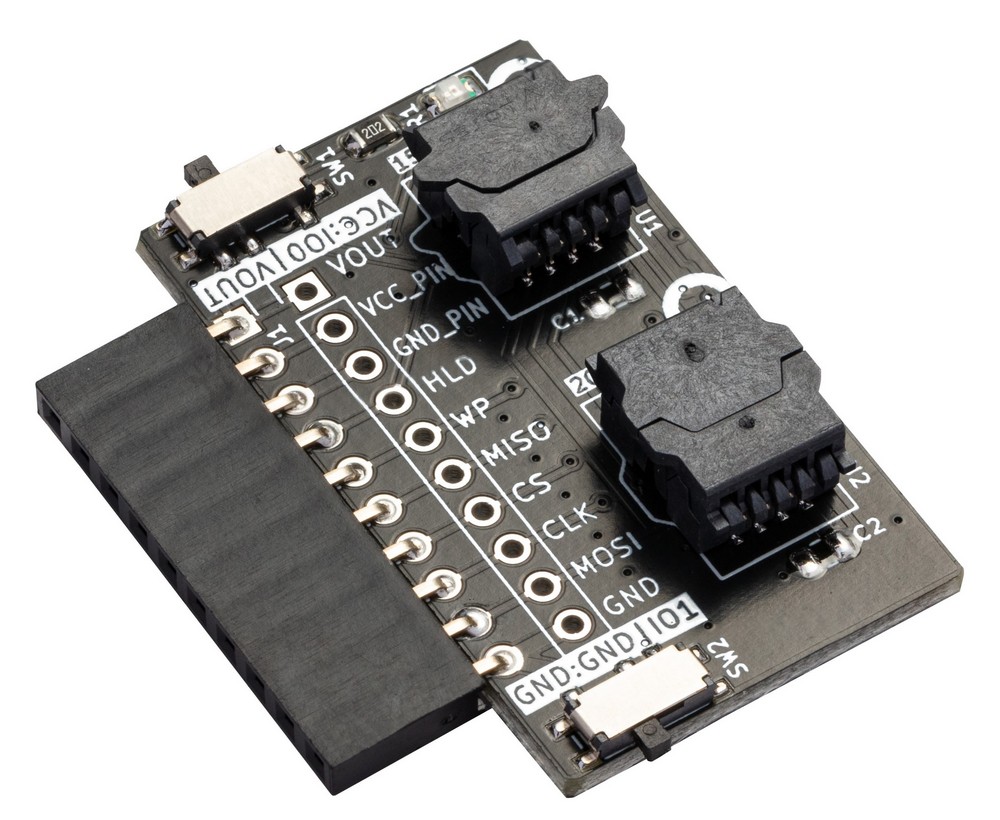
WSON8 SPI Flash Adapter
Lead-less WSON 5x6/6x8 flash chips are becoming more common, but are a bit more expensive than SOP8 chips. The sockets are significantly more expensive than other sizes. We're doing small batches, so our cost is pretty high. If you need something more affordable, look for a WSON8 to DIP8 adapter on your favorite China stuff shopping site and use it with the DIP8 adapter below.
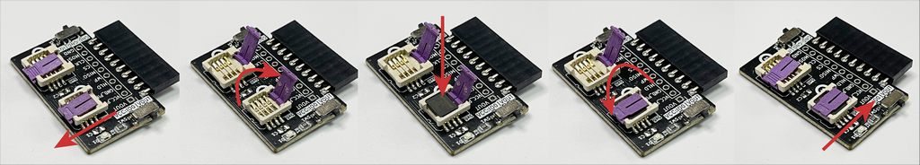
Inserting a chip:
- Push the retaining clip forward to unlock, then lift up to open the socket.
- Place the chip in the socket with the chip pin 1 marker (dot, stripe, etc) aligned with the socket pin 1 marker.
- Swing the retaining clip down, then push it back to lock the socket.
Removing a chip:
- Push the retaining clip forward to unlock, then lift up to open the socket.
- Gently lift the chip out of the socket with tweezers, or turn the socket over and let the chip fall into your hand.
- Swing the retaining clip down, then push it back to lock the socket.
DIP8 SPI Flash Adapter
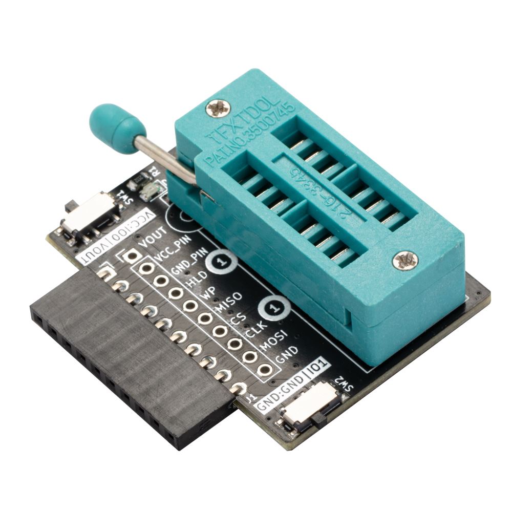
New through hole DIP flash chips are getting rare, but they’re everywhere in vintage computers. These 16P aquamarine ZIF sockets are the universal programming solution. Pull up the little lever, drop in a chip, and push the level down to lock the chip in place.
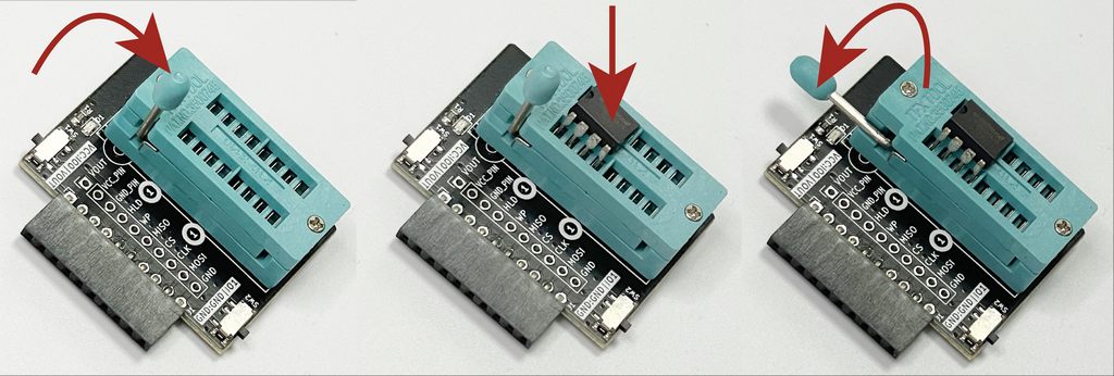
Inserting a chip:
- Pull up the lever to open the socket.
- Place the chip in the socket with the chip pin 1 marker (dot, stripe, etc) aligned with the socket pin 1 marker.
- Push the lever down to lock the chip in place.
Removing a chip:
- Pull up the lever to open the socket.
- Gently lift the chip out of the socket.
- Push the lever down to lock the socket.
Power and Ground Selection
| Switch | Normal | IO pin | Description |
|---|---|---|---|
| VCC | VOUT | IO0 | Connect VCC pin (8) of the socket to VOUT or IO0 |
| GND | GND | IO1 | Connect GND pin (4) of the socket to GND or IO1 |
SW1 and SW2 along the side of the adapter select the power (VCC) and ground (GND) connection to the chip socket. For normal use select VCC:VOUT and GND:GND. If a chip has a non-standard pinout it is possible to connect the VCC and GND pins of the socket to Bus Pirate pins IO0 and IO1.
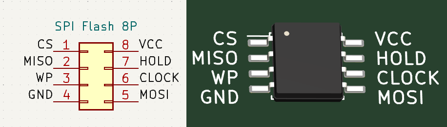
Pin Connections
| Bus Pirate | DIP/WSON/SOP8 | SPI Flash Adapter | Description |
|---|---|---|---|
| Vout | 8 | VCC | Bus Pirate power supply to socket VCC |
| IO0 | 8 | VCC | Pin IO0 to socket VCC |
| IO1 | 4 | GND | Pin IO1 to socket GND |
| IO2 | 7 | HOLD | Hold pin |
| IO3 | 3 | WP | Write protect pin |
| IO4 | 2 | MISO | Master In Sub Out |
| IO5 | 1 | CS | Chip Select |
| IO6 | 6 | CLK | Clock |
| IO7 | 5 | MOSI | Master Out Sub In |
| GND | 4 | GND | Bus Pirate ground to socket ground |
Resources
- SOP8 SPI Flash Adapter schematic and PCB
- LOTES SOP8 SPI Flash adapter schematic and PCB
- WSON8 SPI Flash Adapter schematic and PCB
- DIP8 SPI Flash Adapter schematic and PCB
- flash command documentation
- How to interface common SPI flash chips
Get Bus Pirate 5
- Browse Complete Bus Pirate hardware collection
- Bus Pirate 5 REV10 with enclosure
- Probe Cable Kit
- Auxiliary Cable Kit
- Quick Connect Adapter
Community
Documentation
See the latest Bus Pirate documentation. This site is no longer updated.
Here's some other fun stuff you might enjoy.