AT24C256 I2C EEPROM board
See the latest version. This site is no longer maintained.
See the latest version for up-to-date documentation. Docs have been completely reworked and moved to a new location. The new site is more user-friendly and searchable. It's also easier for the developers to work with.
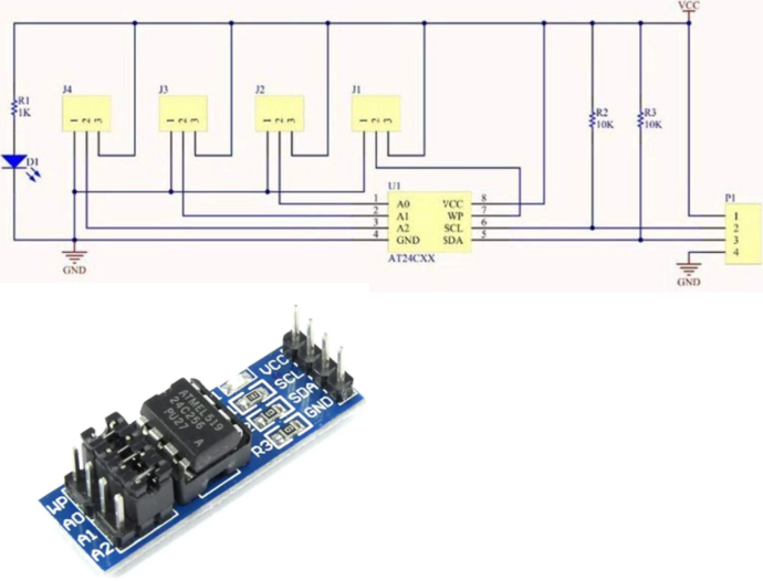
The infamous cheap AT24C256 I2C EEPROM board provides 32K bytes of storage for your projects:
- Cost: ~$2
- Size: 32768 bytes
- VCC: 2.7 - 5.5V
- It includes I2C pull-ups
- Speeds: 1 MHz (5V), 400 kHz (2.7V, 2.5V)
- 64-byte Page Write Mode (Partial Page Writes Allowed).
- I2C address ranges from 0x50 to 0x57 and can be configured using the A jumpers (A0-A2)
Connections
| Bus Pirate | AT24C256 board | Description |
|---|---|---|
| SDA | SDA | I2C Data |
| SCL | SCL | I2C Clock |
| Vout/Vref | VCC | 5volt power supply |
| GND | GND | Ground |
Setup
Considering:
- AT24C256's datasheet max speed
- AT24C256 board pull-ups are 10k
- You've purchased a low-quality clone from AliExpress or any other source
- The length of the Bus pirate cable
We're going to be very conservative and operate at:
- 5V, 100kHz.
- Max current: 50ma.
Since the AT24C256 board already includes pull-ups, there's no need to utilize the pull-ups from the Bus Pirate. If you're using the chip alone (socket adapter, breadboard...) you must activate the Bus Pirate's pull-ups (using the 'P' command) and also connect WP, A0, A1, and A2 to GND.
Mode selection
1. HiZ
2. 1-WIRE
3. UART
4. I2C
5. SPI
6. LED
x. Exit
Mode > 4
I2C speed
1KHz to 1000KHz
x. Exit
KHz (400KHz*) > 100
Data bits
1. 8*
2. 10
x. Exit
Bits (1) >
Mode: I2C
I2C> W
Power supply
Volts (0.80V-5.00V)
x to exit (3.30) > 5
5.00V requested, closest value: 5.00V
Set current limit?
y
Maximum current (0mA-500mA)
x to exit (100.00) > 50
50.0mA requested, closest value: 50.0mA
Power supply:Enabled
Vreg output: 4.9V, Vref/Vout pin: 4.9V, Current sense: 9.2mA
I2C>
- Use the
mmode command and select I2C - Configure I2C for 100kHz and 8bits of data
- Enable the onboard power supply with the
Wcommand, and configure it for 5volts output. - Select a current limit of at least 50mA.
Partial write
We'll write three bytes - 0x41, 0x42, 0x43 - to the EEPROM at memory location 0x69.
I2C START
TX: 0xA0 ACK 0x00 ACK 0x69 ACK 0x41 ACK 0x42 ACK 0x43 ACK
I2C STOP
I2C>
[Begin with an I2C START0xA0is the I2C device address.0x00 0x69is the memory address where we intend to write. The AT24C256 has a 16bit/2byte address range.0x41 0x42 0x43are the three data bytes we want to write.]End with an I2C STOP
After initiating a data write to the EEPROM, you must wait up to 5ms to ensure that the write cycle is complete before starting another. If you enter the write and read commands on separate lines there will be plenty of delay for the write to complete, but if you enter it on a single line be sure to add a 5ms delay between the commands with D:5.
If the writing process fails, check all connections. A0, A1, A2 jumpers must be connected to GND, and ensure that the WP jumper is also connected to GND.
Reading three bytes
We'll read three bytes from the EEPROM at memory location 0x69. To achieve this, two commands are necessary.
I2C START
TX: 0xA0 ACK 0x00 ACK 0x69 ACK
I2C STOP
I2C>
First, use a write command with no data to to indicate the memory address we want to read.
[Begin with an I2C START0xA0is the I2C device write address.0x00 0x69is the 16bit/2byte memory address to read.]End with an I2C STOP
I2C START
TX: 0xA1 ACK
RX: 0x41 ACK 0x42 ACK 0x43 NACK
I2C STOP
I2C>
Second, use the I2C read address to read the bytes from that memory location.
[Begin with an I2C START0xA1is the I2C device read address to access data at the location we set with the previous command.r:3reads back three bytes of data. Bytes read: 0x41 0x42 0x43.]End with an I2C STOP
If the reading process fails, check all connections. A0, A1, A2 jumpers must be connected to GND.
Get Bus Pirate 5
- Browse Complete Bus Pirate hardware collection
- Bus Pirate 5 REV10 with enclosure
- Probe Cable Kit
- Auxiliary Cable Kit
- Quick Connect Adapter