TSL2561 Light Sensor
See the latest version. This site is no longer maintained.
See the latest version for up-to-date documentation. Docs have been completely reworked and moved to a new location. The new site is more user-friendly and searchable. It's also easier for the developers to work with.
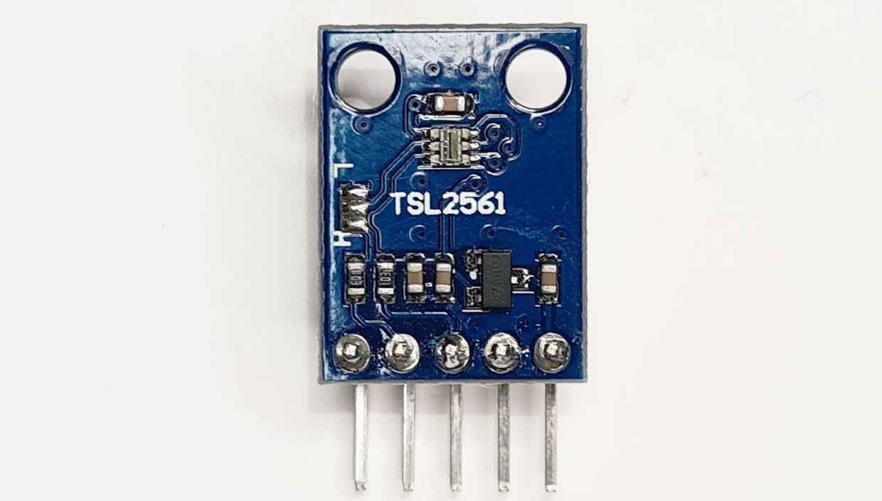
TSL2561 is a light sensor that measures visible and infrared light. It's used in mobile phones, laptops, and other devices to adjust screen brightness. It's also used in street lights to adjust brightness based on ambient light levels.
Connections
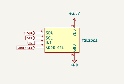
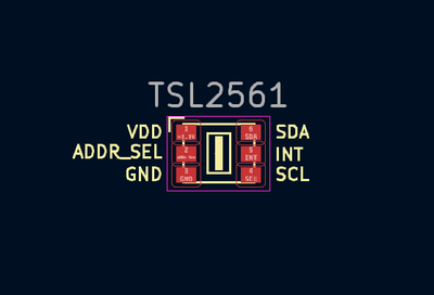
| Bus Pirate | TL2561 | Description |
|---|---|---|
| SDA | SDA | I2C Data |
| SCL | SCL | I2C Clock |
| Vout/Vref | VDD | 3.3volt power supply |
| GND | GND | Ground |
Device address
| ADDR SEL (Pin 2) | Address |
|---|---|
| GND | 0101001x |
| Float | 0111001x |
| VDD | 01001001x |
Pin 2 (ADDR SEL) determines the I2C address of the TL2561. The default address is 0x39 (111001). The address can be changed by connecting the ADDR SEL pin to VDD or GND.
If you're using a breakout board without a datasheet, you can use the Bus Pirate I2C address search marco (1) to find the device.
Setup
Mode selection
1. HiZ
2. 1-WIRE
3. UART
4. I2C
5. SPI
6. LED
x. Exit
Mode > 4
I2C speed
1KHz to 1000KHz
x. Exit
KHz (400KHz*) >
Data bits
1. 8*
2. 10
x. Exit
Bits (1) >
Mode: I2C
I2C> W
Power supply
Volts (0.80V-5.00V)
x to exit (3.30) >
3.30V requested, closest value: 3.30V
Set current limit?
n
Power supply:Enabled
Vreg output: 3.3V, Vref/Vout pin: 3.3V, Current sense: 4.3mA
I2C> P
Pull-up resistors: Enabled (10K ohms @ 3.3V)
I2C>
- Use the
mmode command and select I2C - Configure I2C for 400kHz and 8bits of data
- Enable the onboard power supply with the
Wcommand, and configure it for 3.3volts output. Optionally select a current limit of at least 50mA. - Enable the onboard pull-up resistors with the
Pcommand.
Register map
| Address | Name | Function |
|---|---|---|
| -- | COMMAND | Points to the register to read and write (0x00-0x0F) |
| 0x00 | CONTROL | Control options |
| 0x01 | TIMING | Gain and integration time |
| 0x0A | ID | Part number and revision |
| 0x0C | DATA0LOW | Low byte of ADC channel 0 |
| 0x0D | DATA0HIGH | High byte of ADC channel 0 |
| 0x0E | DATA1LOW | Low byte of ADC channel 1 |
| 0x0F | DATA1HIGH | High byte of ADC channel 1 |
This is a partial register map showing the addresses we'll need to configure and control the TSL2561.
| bit 7 | bit 6 | bit 5 | bit 4 | bit 3 | bit 2 | bit 1 | bit 0 |
|---|---|---|---|---|---|---|---|
| CMD | CLEAR | WORD | BLOCK | ADDR[3] | ADDR[2] | ADDR[1] | ADDR[0] |
The address written to the command register points to the register for the next read/write.
- The command register is accessed by setting bit 7 (CMD) of the command to 1.
- Because bit 7 controls access to the command register, bit 7 is always 0 for any other commands written to other registers.
- The lower four bits of the command register are the address of the register to read or write.
- For the sake of brevity, CLEAR and WORD are set to 1, and BLOCK is set to 0.
Start device
| bit 7 | bit 6 | bit 5 | bit 4 | bit 3 | bit 2 | bit 1 | bit 0 |
|---|---|---|---|---|---|---|---|
| - | - | - | - | - | - | Power1 | Power0 |
TSL2561 starts in power down mode. To start the device, write 0x03 (0b11) to the control register.
Select CONTROL register
I2C START
TX: 0b01110010 ACK 0b11100000 ACK
I2C STOP
I2C>
First, we need to write the address we wish to access to the command register.
[Begin with an I2C START0b01110010I2C write address for the TSL2651 (ADDR pin floating)0b11100000Write command register. Bit 7 set to 1, control register address (0x00/0b000) set in bits 3:0]End with an I2C STOP
Start command
I2C START
TX: 0b01110010 ACK
TX: 3 ACK
I2C STOP
I2C>
Next, we write 0x03 to the control register to start the device. The control register is already selected, so we only need to write the value 0x03.
[Begin with an I2C START0b01110010I2C write address for the TSL2651 (ADDR pin floating)3Write 0x03 to the control register]End with an I2C STOP
Confirm start
I2C START
TX: 0b01110011 ACK
RX: 0x33 NACK
I2C STOP
I2C>
Finally, we read the control register to confirm the device is running. The control register is already selected, so we only need to read the value.
[Begin with an I2C START0b01110011I2C read address for the TSL2651 (ADDR pin floating)rRead the control register]End with an I2C STOP
The control register value is 0x33, the lower 2 bits are high (0x03) indicating the device is running.
Configure gain and integration time
| bit 7 | bit 6 | bit 5 | bit 4 | bit 3 | bit 2 | bit 1 | bit 0 |
|---|---|---|---|---|---|---|---|
| -- | -- | -- | GAIN | -- | -- | INTEG1 | INTEG0 |
The timing register configures the gain and integration time.
- Gain is 1x (0) or 16x (1). 16x gain helps measure in very low light levels. The default is 1x (0).
- Integration time (INTEG1:0) sets how long the sensor collects light measurements. 13.7ms (00), 101ms (01), 402ms (10). Shorter integration times help measure in very high light levels. The default is 402ms (10).
We're going to use the default values. You can skip the configuration step if you like.
Select TIMING register
I2C START
TX: 0b01110010 ACK 0b11100001 ACK
I2C STOP
I2C>
Like the control register, first we set the command register to point at the timing register (0x01).
[Begin with an I2C START0b01110010I2C write address for the TSL2651 (ADDR pin floating)0b11100001Write command register. Bit 7 set to 1, timing register address (0x01/0b001) set in bits 3:0]End with an I2C STOP
Write TIMING register
I2C START
TX: 0b01110010 ACK 0b00000010 ACK
I2C STOP
I2C>
Now configure the gain and integration time. Gain (bit 4): set to 0 (1x). Integration time (bits 1:0): set to 10 (402ms).
[Begin with an I2C START0b01110010I2C write address for the TSL2651 (ADDR pin floating)0b00000010Write timing register. Bit 7 set to 0, gain (bit 4) set to 0, integration time (bits 1:0) set to 10]End with an I2C STOP
Measure light
Once started the TSL2561 takes continuous light measurements with an ADC and stores them in the DATA0 and DATA1 registers.
TSL2561 has two light sensors. One measures all light, the other measures infrared light only. The infrared value is used to compensate for light that isn't visible to the human eye.
Select DATA0LOW register
I2C START
TX: 0b01110010 ACK 0b11101100 ACK
I2C STOP
I2C>
First, use the command register to select the DATA0LOW register (0x0C/0b1100) with bit 7 set to 1.
[Begin with an I2C START0b01110010I2C write address for the TSL2651 (ADDR pin floating)0b11101100Write command register. Bit 7 set to 1, DATA0LOW register address (0x0C/0b1100) in bits 3:0]End with an I2C STOP
Read DATA registers
I2C START
TX: 0b01110011 ACK
RX: 0x43 ACK 0x00 ACK 0x0C ACK 0x00 NACK
I2C STOP
I2C>
We've arrived! It's time to read out the light sensor measurements. Each sensor measurement has a low and high byte, so we'll need to read 4 bytes (2 sensors, 2 bytes each).
[Begin with an I2C START0b01110011I2C read address for the TSL2651 (ADDR pin floating)r:4Read 4 bytes]End with an I2C STOP
The data is read low byte first, followed by the high byte. Here, the measurements are 0x0043 and 0x000C.
Convert to LUX
=0x43 =67 =0b01000011= 'C'I2C>
- Use the
=convert number format command to find the decimal equivalent of 0x0043 (channel 0) and 0x0000C (channel 1) for easier calculation (67/12).
ratio=chan1/chan0
ratio=12/67
ratio=0.1791044776
LUX is calculated by finding the ratio of the two channels, then using the ratio to select the correct formula.
| Ratio Range | Calculation |
|---|---|
| <= 0.125 | Lux/(Chan0*16) = 0.0304 - 0.0272*(ratio) |
| <= 0.250 | Lux/(Chan0*16) = 0.0325 - 0.0440*(ratio) |
| <= 0.375 | Lux/(Chan0*16) = 0.0351 - 0.0544*(ratio) |
| <= 0.50 | Lux/(Chan0*16) = 0.0381 - 0.0624*(ratio) |
| <= 0.61 | Lux/(Chan0*16) = 0.0224 - 0.031*(ratio) |
| <= 0.80 | Lux/(Chan0*16) = 0.0128 - 0.0153*(ratio) |
| <= 1.30 | Lux/(Chan0*16) = 0.00146 - 0.00112*(ratio) |
| > 1.30 | Lux/(Chan0*16) = 0 |
Our ratio is greater than 0.125 and less than 0.250, so we'll use the second formula.
By default the TSL2561 gain is set to 1. For this calculation we need to multiply the channel0 value by 16 to compensate for the gain. If the gain is set to 16, the channel0 value is multiplied by 1.
lux/(chan0*16)=0.0325-0.0440*(ratio)
lux/67*16=0.0325-0.0440*(0.1791044776)
lux/1072=0.0325-0.0078801987
lux/1072=0.0246198013
lux=0.0246198013*1072
lux=26.38
The compensated LUX value is 26.38.
There's lots of other goodies in the TSL2561. High and low levels of light can trigger an interrupt on the INT pin. Gain and sensing time (integration time) can be configured to get accurate readings in different light levels. This walk through gets you started, but there's lots more to explore in the datasheet.
Read version
The ID register contains the part number and revision of the TSL2561.
Select ID register
I2C START
TX: 0b01110010 ACK 0b11101010 ACK
I2C STOP
First, use the command register to select the ID register (0x0A/0b1010) with bit 7 set to 1.
[Begin with an I2C START0b01110010I2C write address for the TSL2651 (ADDR pin floating)0b11101010Write command register. Bit 7 set to 1, ID register address (0x0A/0b1010) in bits 3:0]End with an I2C STOP
Read ID register
I2C START
TX: 0b01110011 ACK
RX: 0x50 NACK
I2C STOP
I2C> = 0x50
=0x50 =80 =0b01010000= 'P'
I2C>
Now read back the device ID and revision.
[Begin with an I2C START0b01110011I2C read address for the TSL2651 (ADDR pin floating)rRead the ID register]End with an I2C STOP
The value is 0x50, which is 0b01010000.
- The part number is the upper four bits: 0b0101 (5)
- The revision is the lower four bits: 0b0000 (0)
Macro
TSL2561 LUX sensor
ID: 5 REV: 0
Chan0: 66 Chan1: 12 LUX: 26
I2C>
Can't get it to work? Need a sanity check? Macro (4) in I2C mode automates the commands on this page.
Get Bus Pirate 5
- Browse Complete Bus Pirate hardware collection
- Bus Pirate 5 REV10 with enclosure
- Probe Cable Kit
- Auxiliary Cable Kit
- Quick Connect Adapter